In some ways, I started this project back in 2015, though the final form didn't come to me until late 2019. What started as a simple idea to light up a sign using off the shelf parts ended up being a years-long journey of lost hardware, multiple companies, 3D modeling, and PCB design.
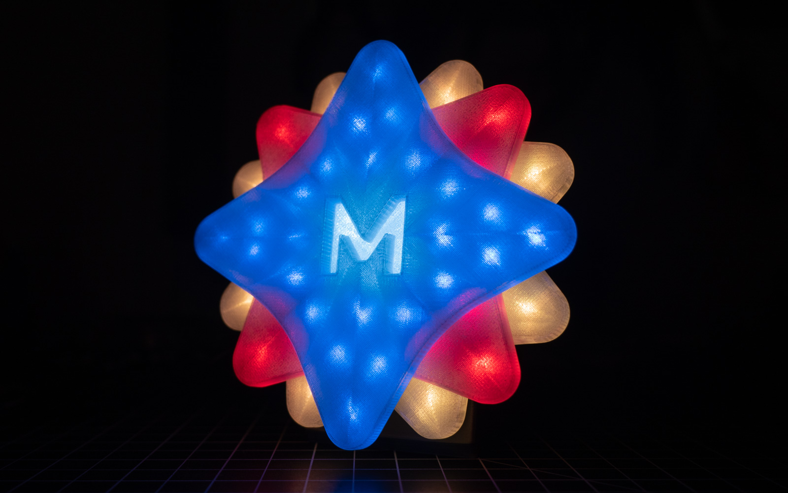
A fully-assembled MetaLamp displaying the "classic" MetaLab colors. But first, some context.
Octopus
In the halcyon days of 2012, I became the first employee of a company called Octopus Creative in Santa Cruz, California. My wife Charlene and I moved to Santa Cruz from our tiny hometown when I got that job, so it was a really big deal for me.
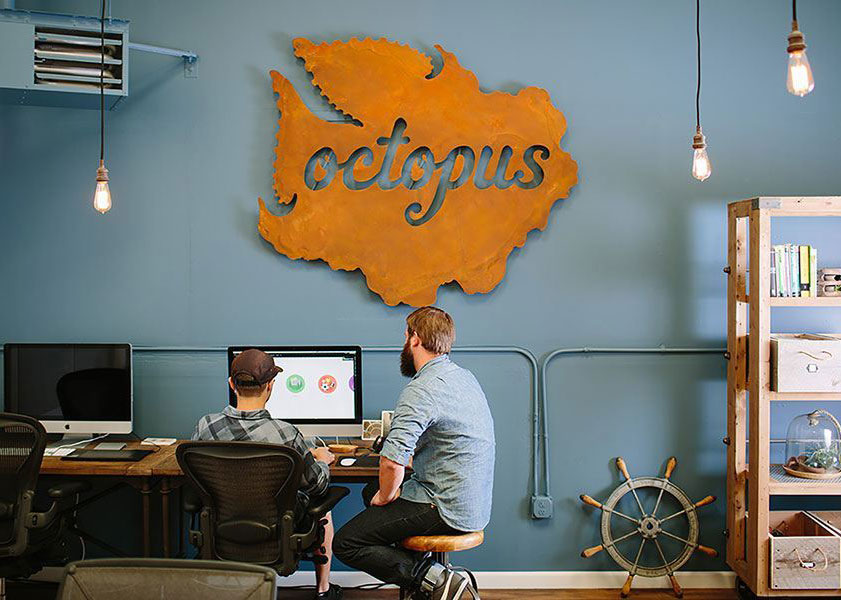
The Octopus sign
Octopus was a digital product company. People would come to us with an idea, and we'd take them from a thought in their head, through sketches, all the way to a real product. A real thing that lived on the Internet or on someone's phone and people used, or even paid to use, every day. It was amazing, and looking back I'm always blown away by how much incredible work that bunch of basically just-out-of-college kids produced.
At one point, we got a huge metal sign of the Octopus logo to hang in the office. I got the idea in my head that the sign would look much better with some custom LED lighting, because what doesn't, right? I'd started playing with hardware via the Arduino ecosystem a couple years before, and felt like I'd learned enough to ship a usable product. I approached the founder of Octopus, James Hobbs. "James," I said, "I'm gonna buy some lights, and some microcontrollers, and I'm gonna light that sign up!" James approved, and so I got started.
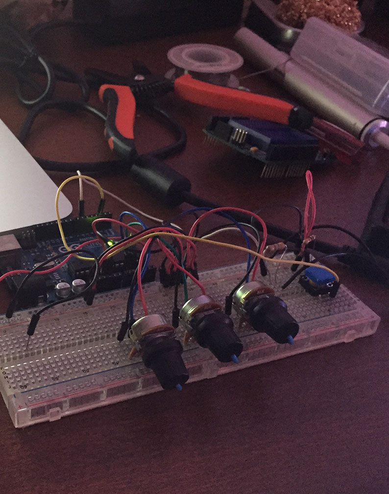
An early picture of the controls (RGB dials) for the Octopus lights. Unfortunately, I don't have much test footage from this time.
I dreamed up all sorts of features like a music visualizer that pulsed while we worked, custom patterns, manual color controls; the list went on. I actually got most of it working, but I was never totally happy with the mounting situation, or some other aspect. Basically, I was just too precious about it given my abilities at that point.
Time went on, and I ended up leaving Octopus to move to San Francisco. I kept working on the light, though, and eventually finished it. I was really excited to finally hand it off. The timing was perfect, because I was just about to head to a conference some Octopus folks were attending. I packed the lights up, brought them along, and then completely forgot to hand them off during the conference. On arriving home, I proceeded to leave the lights in the rental car, never to be seen again.
MetaLab
After losing the original Octopus lights, the lighting project kind of fell out of my mind. Octopus eventually shut down,1 and I spent a couple years living in a van. That wasn't exactly ideal for working on non-van-related electronics projects, though I did manage to make some pretty slick HomeKit-compatible lights!
After our travels in the van, Charlene and I decided to settle down in Portland, Oregon in early 2019. James had also ended up in Portland, so of course we ended up talking and meeting up. At this point, James had joined MetaLab as a Design Director (and shortly after that, promoted to VP of Design). We'd both been huge fans of MetaLab's work since before we'd even met, so I knew this was a big deal for him.
The first demo footage of the React Native application controlling MetaLamp over Bluetooth.
Soon after, I noticed a role on the MetaLab website that sounded similar to the work I'd done at Octopus. I mentioned it to James, who agreed it sounded like a good fit. I applied, interviewed, and eventually got the job.
One of the things MetaLab and Octopus have in common is that they both have full closures for the last bit of the year ("the week between"). Most client teams, at least in North America, are away during this time anyhow. Not much tends to happen, so it just makes sense to take that time to reflect and recharge.
A personal tradition I started at Octopus is using that end of year break to learn a new skill, or practice a particular aspect of an existing one. I've used past breaks to learn new programming languages, build game prototypes/proof of concept game engines, etc. For 2019's break, I decided I finally wanted to learn more skills that had physical outputs, so I dove into an area I'd been following for many years and purchased a 3D printer. In order to actually design whatever popped into my head, I also started learning 3D modeling, using Fusion 360.
Around this time, I started thinking about the Octopus sign again, and decided I wanted to use this new skill to build an updated light for James, since I'd never been able to deliver on the original project.
Hardware is hard
The MetaLab logo is a compass rose with 16 points, and an "M" in the center. I decided the new project would be a desk ornament of the logo, where the color of each point was controllable via Bluetooth and a mobile app.
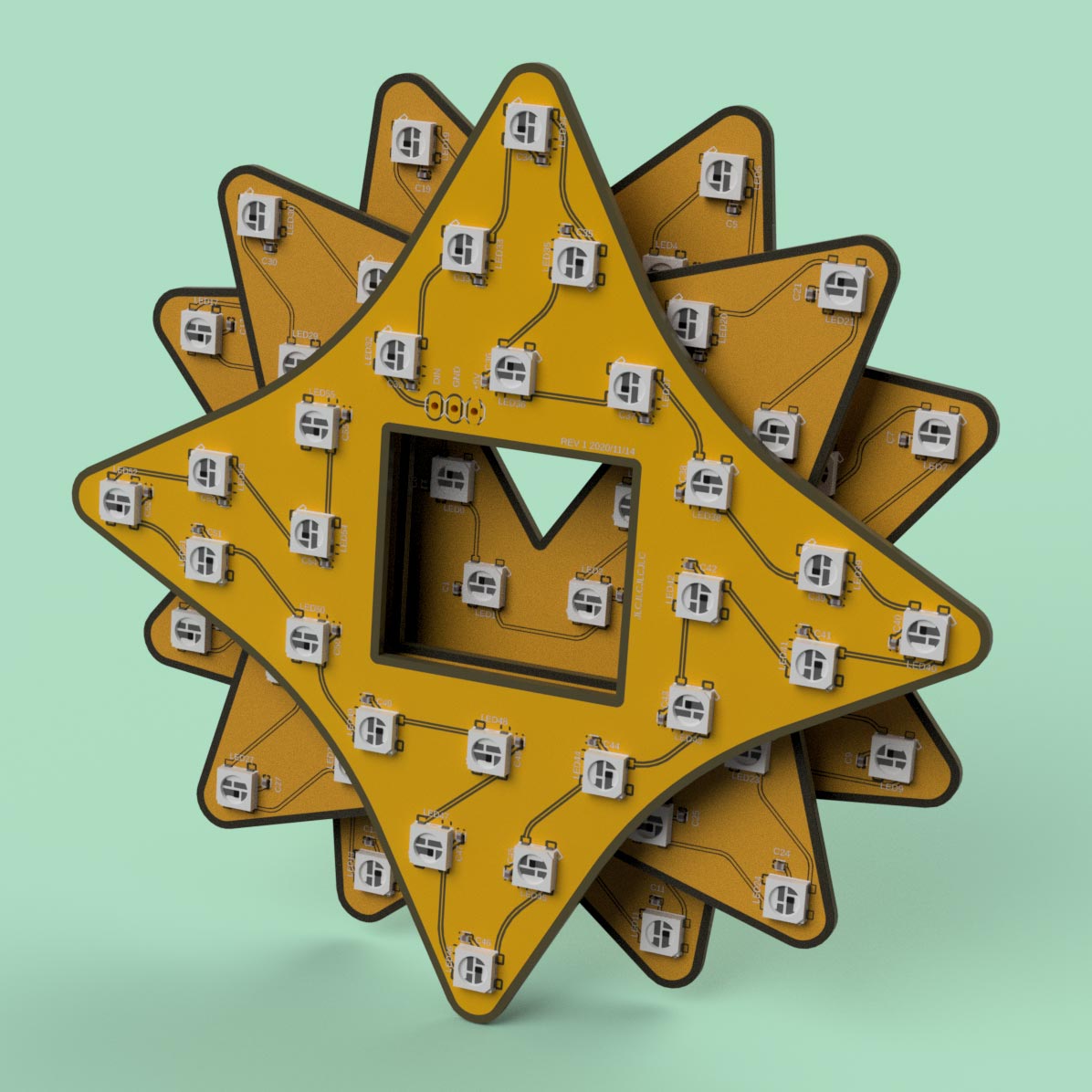
The three PCBs that make up the points of the MetaLab logo.
Initially, I thought I would just model a case, and install pre-assembled NeoPixel WS2812B breakout boards with hand wiring. Unfortunately, I ran into all sorts of issues with these boards. After many hours lost debugging, I decided it made more sense to learn PCB design (another skill I'd been putting off for years), and fix the problem at a lower level.
I ordered all the PCBs for this project from JLCPCB in China. I was impressed by pretty much every aspect of that experience. As a newcomer, I really had no idea what to expect here. During this project, I placed three orders from them. Every time, they provided boards very quickly, at what I consider a super reasonable price.
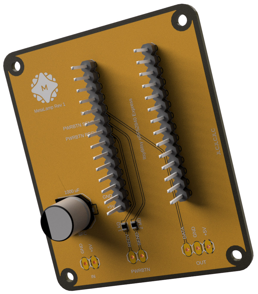
The microcontroller carrier board. I forgot a resistor on the data line for this run, so I've just added that inline with the wire that goes to the other PCBs.
For a single PCB design with surface mount part installation (in my case, LEDs, resistors, and capacitors), it cost about $50 USD, including shipping (for a minimum order of 5 PCBs). For a run of all four PCBs with assembly and shipping, it would cost around $100 USD. Considering that custom machined PCBs cost many thousands of dollars when I was a kid, I'm really blown away by what's possible now.
When JLC had questions about the design files I provided, they were quick to reach out via email with questions and confirm that everything was correct. My orders took around a week from the time I submitted them until I had them in hand.
This project would have also been much more difficult without help from Rockwell Schrock. He was a huge helping hand throughout on the hardware design side, assisting me with lots of big questions and struggles.
A walkthrough of the electronics inside the first run of MetaLamps
Embarrassingly, I misread the WS2812B datasheet for the original PCB run, missing some required capacitors. This gave the first set of front panel PCBs a flicker at certain color/brightness values. A quick change to the PCB design in Fusion fixed that, and after confirming the fix, I was able to design the remaining three PCBs over a weekend.
In total, MetaLamp has 56 WS2812B packages in it (168 total LEDs, accounting for the individual red, green, and blue LEDs in each package). I also added a capacitive power button to quickly toggle it on and off without having to open the companion app.2
Back in My Own Domain
A walkthrough of the React Native application. The app includes color changing, preset management (create/rename/delete), and automatic reconnection to your last-used MetaLamp.
At first, I was going to try to make a native BLE iOS app by following example code from Adafruit, though my experience is mostly in web development. I made some decent progress with this during the early part of the year. Around March, however, I ended up needing to learn React Native for some work projects, which turned out to be a great fit for MetaLamp as well.
I was able to put together a React Native application for iOS (James' platform of choice) in a couple weeks of nights and weekends, and get it talking to an Adafruit Feather nRF52840 Express (In the "final" product, I switched to the smaller ItsyBitsy nRF52840 Express). My familiarity with the software side of things proved useful, and at this point, I was feeling quite good about the project.
This was the first time I'd used MobX, and while it wasn't without its quirks, overall I was very impressed and happy with it for this simple use case. It's a more natural way to work with shared state in a reactive context than Redux, to my mind.
Beyond the basics of being able to scan for, connect to, and set colors on a MetaLamp, the app provides some additional benefits. It lets users create and manage preset color schemes, and has a soft power button synchronized to the state of the capactive power button built into MetaLamp.
Modeling & Printing
I went through quite a few physical iterations of MetaLamp as well. Initial designs had "trenches" in each logo layer to hold the manual wiring between each LED. After switching to PCBs, these became trays where the entire board was inset.
The design also evolved as my modeling skills improved throughout the year. Eventually, I landed on a design where each layer of the logo snapped into place above the previous one. This meant no bolts, glue, or other connectors were required to secure the logo together, and it could retain as much of a transulcent look as possible.3
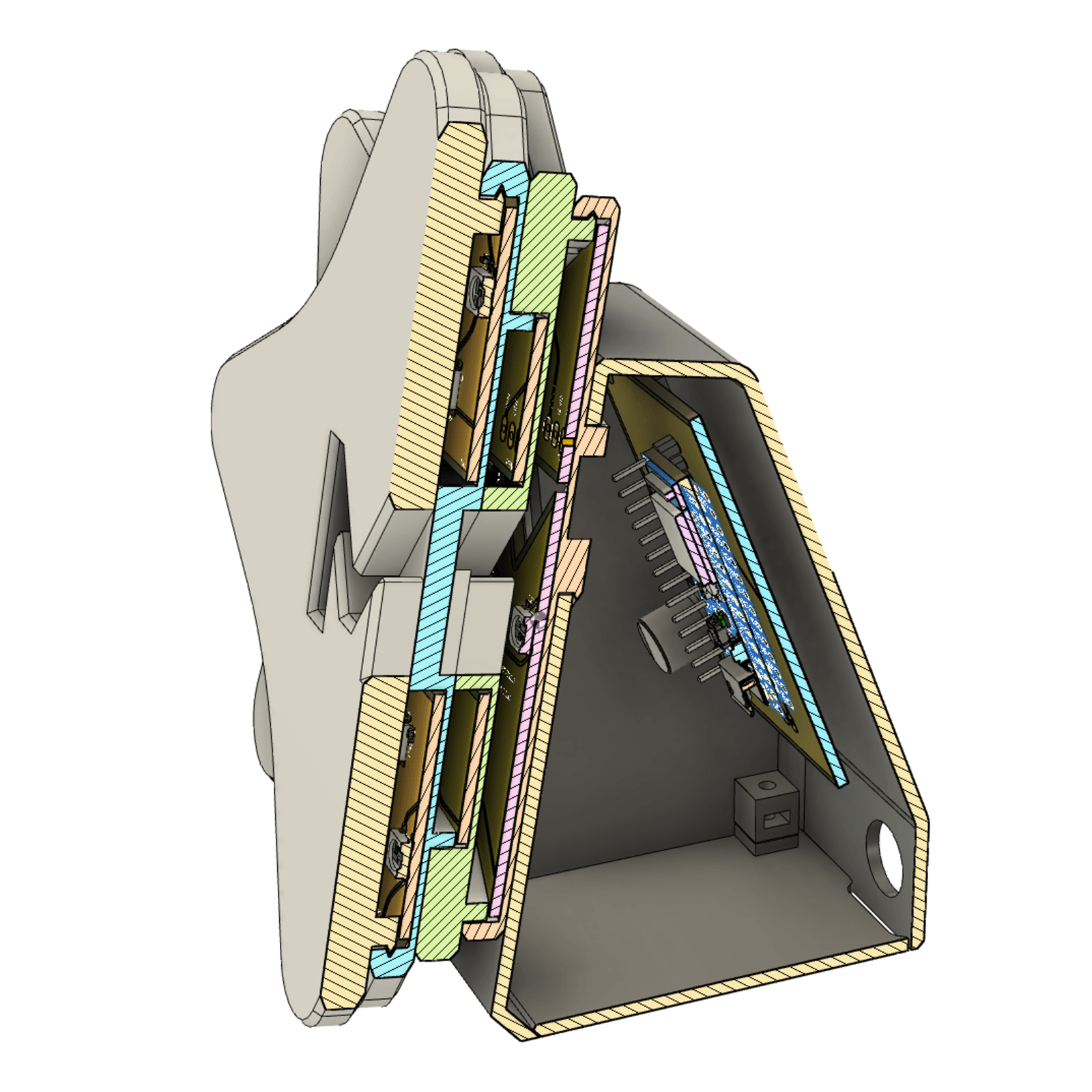
A cross-section of the completed PCBs and 3D model, showing how the segments of the logo clip into each other, and hold the PCBs in place.
An unexpected challenge in this project was getting "clean" transparent prints. The nozzle on my printer would often have small bits of colored filament stuck to it, which could become dislodged while printing the clear segments of the lamp and get stuck in the final print. This ruined a few otherwise great prints. The problem was exacerbated by a shortage of rubbing alcohol due to COVID-19. I looked at several stores throughout the year and was unable to find isopropyl alcohol for more easily and thoroughly cleaning the nozzle.
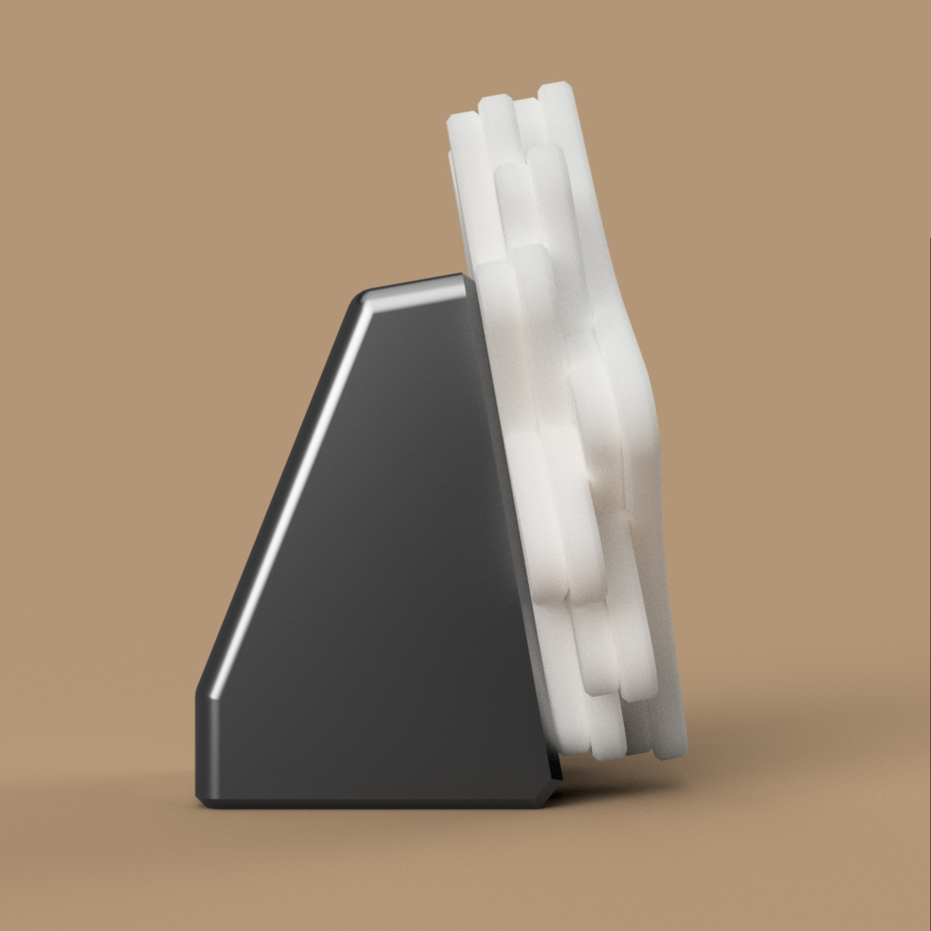
A profile rendering of the finished model.
MetaLab also made a change to the company branding during this time, which meant I had to build out new 3D models from the new logo files. This ended up working out quite well, however, as the new vector files are cleaner than the previous ones, and made for a better model base.
The final design is made of 6 pieces. The logo itself is made of 4 prints, which I've printed in transparent PETG. These snap together, and each one other than the frontmost holds a PCB that illuminates the print in front of it. The entire logo then snaps onto the base, which has a bottom plate that connects using bolts.
No, Really, Hardware Is Hard
As I write this, I'm finishing up the last few prints before assembly and handoff to James. I received the final PCBs about a week and a half ago, and have been running a burn in test since the day I received them. For this testing, I had all four PCBs connected to each other, and turned the whole lamp on every day when I started work, and off at the end of each day (but without disconnecting from power entirely). Sometimes I would use the app throughout the day to swich presets, or unplug/replug the lamp to make sure the last settings were being saved correctly.
A video from my print monitoring software, showing the printer extruding a "Hilbert curve" infill pattern. This example was recorded before I switched from the trench design for manual wiring to custom PCBs.
Everything had been going great, until last night, when I turned the light back on after a period of inactivity. It flashed seemingly random colors, and no LEDs beyond the first few would illuminate correctly. Today, I tried again with the same results, and tried a second rear board that also had issues immediately when it was hooked up. The third of five rear PCBs did work successfully, however, and has been running a NeoPixel strand test all day successfully.
I tried the front and middle boards from that original assembly separately, and both of them still work great. At this point, I'm not sure whether these issues are something to do with the layout of the rear PCB, a manufacturing problem, or something else entirely.
In the meantime, my plan is to assemble another MetaLamp for myself, hand this one off to James, and ask him to let me know if it goes funky at any point. If either of them break, I'll research the issue more and do another run of boards. I'd love for this to be an ongoing project anyway, as it would be great to add more features down the road like animation and music visualization. I fear I'll never learn to avoid my own scope creep.
As things stand now, the overall cost per MetaLamp is around $50 USD. This breaks down to $20 in PCBs + shipping costs (assuming low volume production), $20 for the microcontroller board, and $10 of 3D printer filament, wiring, and other miscellaneous parts. A compatible 5 V DC power adapter adds another $10-15. For a bespoke item like this, I'm pretty astounded at how cheap it can be.
An assembled MetaLamp rose going through "burn-in" testing using a spectrum pattern.
Footnotes
-
The original Octopus sign was sold to a local signage collector. ↩
-
The physical power button is synchronized to the displayed state in the app using BLE notify events. ↩
-
Actually a bit too translucent. I would prefer something that diffused the LED light a little better, so I'll be on the lookout for filament alternatives in the future. I also ended up using a bit of glue to secure the rear plate to the base. In future versions, I'd like to rethink this connection so it feels sturdy enough to work with the snap fit. ↩